Most 3D printing problems are not printer problems — they are modeling problems. A file that looks fine in the viewport can still fail on the bed because the geometry was never built with the actual printing process in mind. We see this constantly when clients send us 3D models for 3D printing, expecting a clean run, and the print fails for a reason that traces back to a decision made in the modeling software.
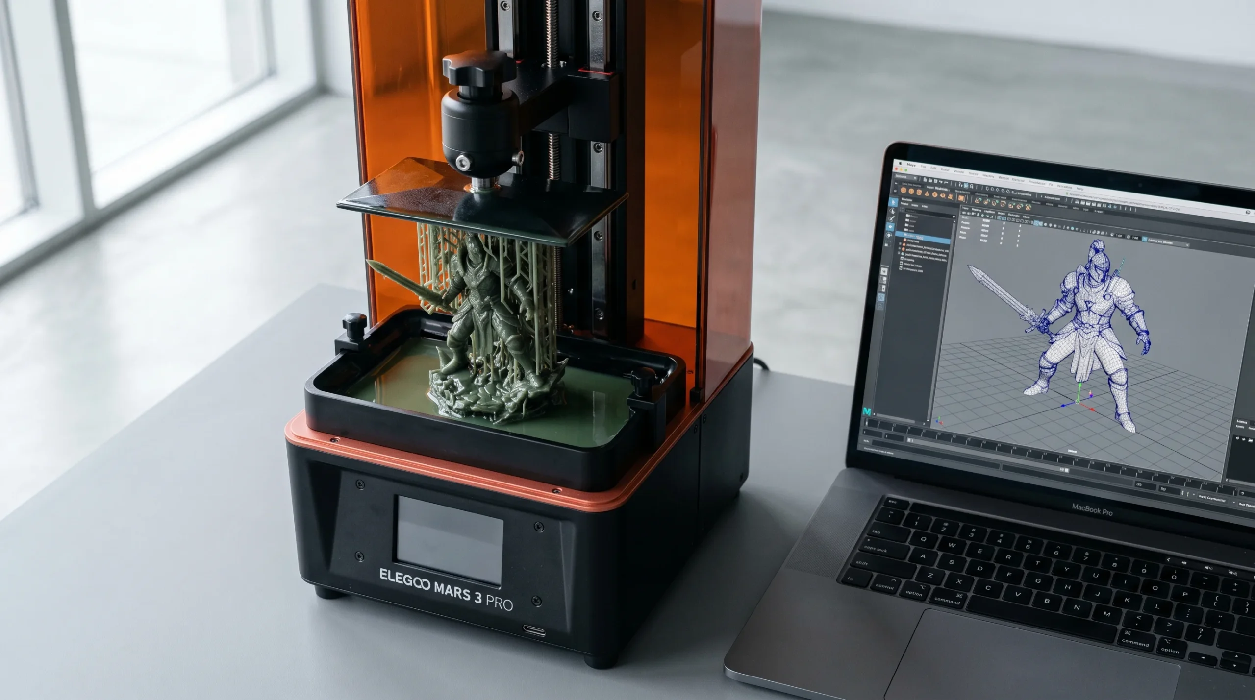
So here is the short list. Five mistakes that account for the majority of failed prints we get asked to rescue, and what to do about each one.
1. Modeling without picking the material first
The material is not a finishing decision. It is a modeling decision, and the order matters.
Print materials behave very differently. Some are brittle, some flex. Some hold sharp detail, some round it off. A thin connector that prints cleanly in nylon will snap off a brass casting. An overhang that survives in PLA needs support in resin. If you model the geometry first and pick the material later, you usually end up reworking the geometry.
- Strong but brittle materials (resins, ceramics, some metals) — round corners, add fillets at stress points, thicken protrusions.
- Flexible materials (TPU, rubber-like resins) — model thinner walls than you would for rigid plastic; the part still holds shape.
- Cast metals (gold, silver, bronze via lost-wax) — design as if you were sculpting wax, because that is essentially what gets printed first.
Pick the material, then model to its rules. Not the other way around.
2. Treating “metal is metal” as if technology doesn’t matter
Stainless steel and sterling silver are both metals. They are printed by completely different processes, and they need different geometry. This trips people up more than the material question itself.
Steel and aluminum on industrial printers usually go through selective laser sintering or DMLS — powder-based, which means interlocking parts and captive geometry are actually doable. Precious metals go through investment casting from a wax or resin master, which means no captive geometry, no interlocked rings, and a single clean shell. Photopolymer resins on stereolithography behave differently again.
The takeaway is blunt: do not assume two materials in the same family share modeling rules. The process determines the rules, not the periodic table. Before you start modeling, find out the exact print technology — not just the material name — and design for that pipeline.
3. Wall thickness — the single most common reason prints fail
If we had to name one issue that we fix on incoming files more than any other, it is wall thickness. Both directions.
Walls that are too thin print as gaps, snap during cleanup, or simply do not resolve at all. The minimum printable wall depends on the technology and material — what works at 0.8 mm in FDM might fail at 0.3 mm in a fine resin print and vice versa.
Walls that are too thick are the less-obvious failure. Thick mass traps heat, shrinks unevenly during curing or cooling, and pulls internal stress into the part. Cracks appear days later, sometimes after the part has been in someone’s hands for a week. Hollowing out thick sections and adding drain holes is almost always the right move.
Check minimum and maximum wall thickness for the specific machine and material before you finalize the model. Generic numbers from a tutorial are a starting point, not a spec.
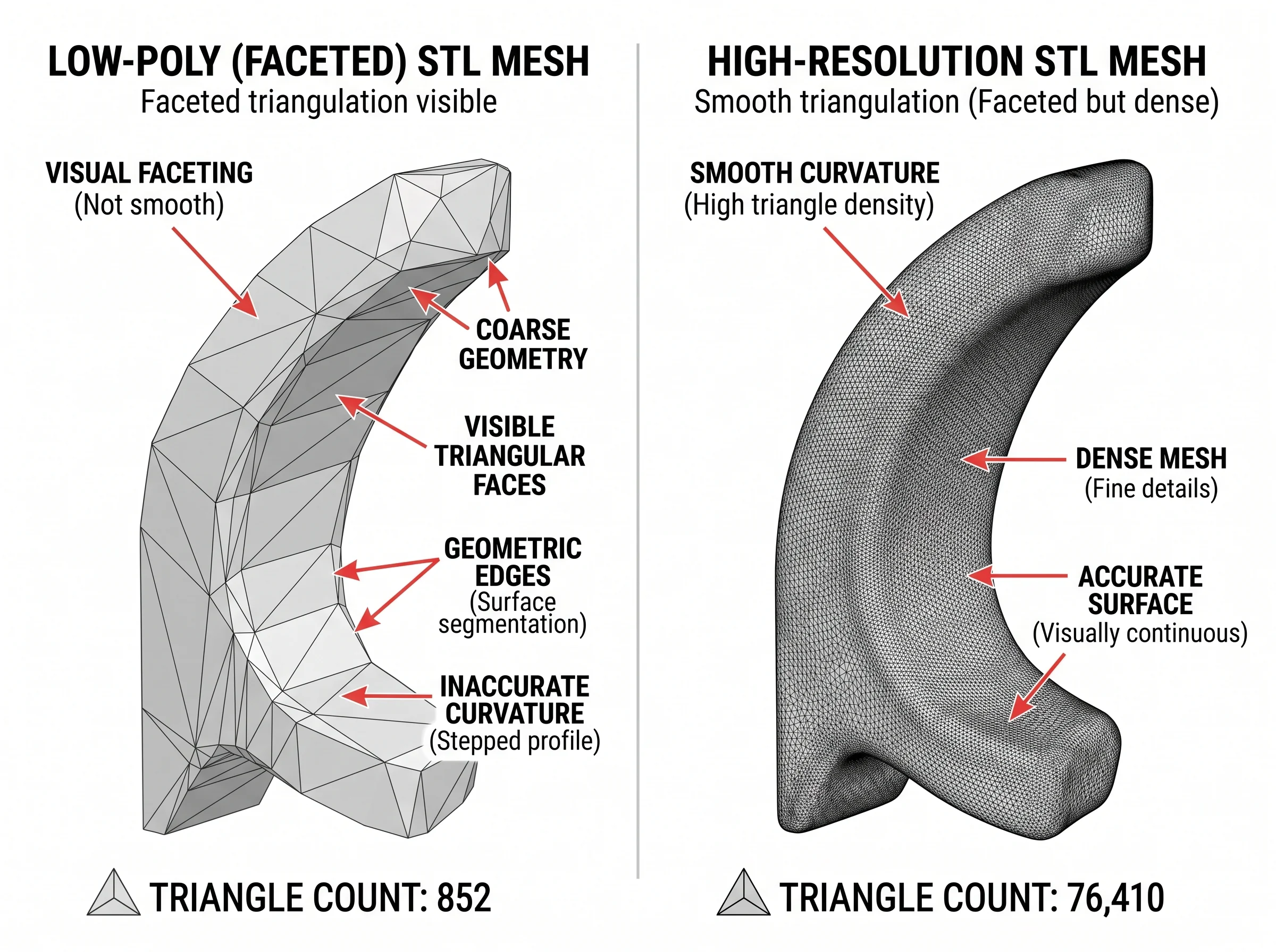
4. Exporting STL at the wrong resolution
STL is still the working file format for most printing pipelines, which means your model is going to be approximated as a mesh of triangles on the way out. The resolution of that approximation matters, and most people set it wrong in one of two ways.
Set it too low and the curved surfaces of the model come out faceted — visible flat panels where you wanted a smooth radius. The print looks pixelated in a physical sense.
Set it too high and the file balloons. The slicer chokes, you wait forever for previews, and you have packed in detail the printer cannot reproduce anyway. There is no point exporting at a tolerance finer than what the machine can actually print.
A practical default for most production work is around 0.01 mm tolerance (deviation between the original surface and the exported mesh). Finer than that and you are paying in file size for resolution that disappears on the print bed. Coarser and you start to see the triangles.
5. Ignoring what your modeling software is — and isn’t — built for
Different software is built for different problems, and they make different assumptions about your geometry. Use the wrong tool and you end up exporting a mesh that looks correct but is unprintable.
- ZBrush — incredible for organic detail and sculpting, but it ships dense meshes that often need decimation and watertight cleanup before printing.
- Blender — flexible, but it does not enforce wall thickness, manifold geometry, or printability. You have to check all of that yourself.
- SketchUp — easy for blocky models, but native geometry frequently has non-manifold edges and missing faces that wreck STL export.
- SolidWorks and other parametric CAD — generally strong for printable geometry because they enforce solids, but resolution settings on STL export still matter.
- Tinkercad and other beginner tools — fine for simple shapes, weaker once you need hollowed parts, infill control, or interior detail.
None of these is wrong. They are just built for different things. The mistake is assuming a model that looks finished in your sculpting tool is automatically print-ready.
What we check when clients send us 3D models for 3D printing
Most of the rescue work we do on incoming files comes down to the same checklist. Manifold geometry. Wall thickness against the chosen material. Overhang angles and support needs. STL tolerance set sensibly for the printer. Holes in the right places to drain liquid resin or trapped powder. A clean shell instead of dozens of overlapping pieces from a sculpting tool.
If you have a model that keeps failing — or a concept you have not modeled yet and want it done right the first time — that is fairly routine work for us. We do this on the design and modeling side, in ZBrush, Blender, 3ds Max, and SolidWorks depending on whether the part is organic or technical. Send the file over, and we can typically give you a quick read on whether it needs a light cleanup or a rebuild from scratch.
One honest scope note: when the project is closer to engineering than design — production tooling, precision industrial mechanisms, certified mechanical parts — we ask for clear drawings or references and limit our work to the modeling side. We do not stamp engineering documents and we do not do structural calculations. For most figurines, decorative items, prototype geometry, and design-side modeling, none of that comes up.
If you want a broader sense of the kind of modeling work we take on, the character modeling for print and action figure modeling articles cover related ground.